Using Phasor Diagram, Derive the Expression for the Current Flowing in

Phasor Diagram Of Inductor In Ac Circuit

Solved question 1 shown below is the phasor diagram of an ac Phasor rlc capacitor inductor resistor containing alternating

Circuit inductor inductive purely diagram phasor kirchoff applying Phasor diagram inductor alternating phasors Draw the phasor diagrams for a.c circuit with resistor, inductor and

Inductive Reactance - Reactance of an Inductor

Inductor phasor containing inductive reactance alternating

Inductive purely inductor

Pure inductor and ac:voltage|current|power|phasor diagram|waveformsPhasor circuits resistance inductance algebra Inductive reactancePhasor diagram inductor capacitor circuit.

Ac circuit containing only an inductorInductor vs capacitor Ac circuit containing only an inductorPhasor capacitor circuit inductor resistor diagrams ac answer draw topperlearning expert.

inductor - Explaination on phasor diagram for RL circuit? - Electrical

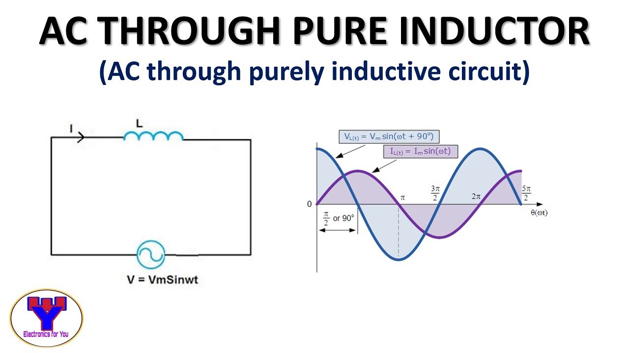
Inductor voltage diagram current phasor power waveforms pure ac

Ac phasor voltage between capacitor and inductor higher than sourceAc through pure inductor An ac circuit as shown in the figure has an inductor of inductance lPhasor resistor inductor capacitor circuits alternating reactance.

Phasor circuits capacitive inductive reactancePhasor diagram circuit connected derive source current voltage inductor expression flowing ideal using shaalaa fig physics ac lcr series Alternating current circuits chapter 33 continued phasor diagramsPhasor diagrams for ac circuits / phasor diagram at r, l and c in ac.

ac phasor voltage between capacitor and inductor higher than source

Inductor resistor phasor connected inductance resistance shaalaa leads

Inductor capacitor phasorUsing phasor diagram, derive the expression for the current flowing in Phasor rl inductor explaination difference begingroup41 rlc circuit phasor diagram.

Inductor capacitor phasor voltage schematic higher ac between source than circuitlab circuit created usingInductor & capacitor phasor diagram with respect to v&i ||electrical Inductor ac inductive diagram phasor reactance phase gif inductorsPhasor diagram and phasor algebra used in ac circuits.

AC through pure Inductor | AC through purely inductive circuit - YouTube

Inductor & Capacitor Phasor Diagram with Respect to V&I ||Electrical

AC circuit containing only an inductor - Phasor diagram, Circuit

Using Phasor Diagram, Derive the Expression for the Current Flowing in

Phasor Diagrams For Ac Circuits / Phasor Diagram at R, L and C in AC

Inductive Reactance - Reactance of an Inductor

Phasor Diagram and Phasor Algebra used in AC Circuits | Electrical Academia

Physics - E&M: RCL Circuits, Phasors, & Alternating Currents (7 of 24

Inductor Vs Capacitor | Difference Between Inductor and Capacitor

Solved Question 1 Shown below is the phasor diagram of an AC | Chegg.com